
The NHBC guidelines for strip and trench fill foundations provide the following key points:
Compliance
Strip and trench fill foundations must comply with the Technical Requirements and adequately support load-bearing elements. They should be designed by an engineer according to Technical Requirement R5 in certain situations.
Provision of information
Clear and detailed designs and specifications should be produced and distributed to relevant personnel. Ground conditions and any special features should be taken into account, and information on them should be provided to NHBC.
Ground conditions
Foundations should be of suitable depth, taken to a suitable bearing stratum, and consider factors such as home design, layout, and ground conditions. Special considerations should be given to frost-susceptible soils and shrinkable and volume change soils.
Hazardous ground
Foundations on hazardous ground should be designed by an engineer, and NHBC should be notified in advance.
Setting out
Foundations should be accurately set out, with control measurements of trenches and proper checking of dimensions and levels.
Services and drainage
Foundations should protect existing services and accommodate drainage and other services. Proper provisions should be made for existing services and ground water drainage.
Safe transmission of loads
Foundations should transmit loads safely without excessive settlement, considering dead and imposed loads. Foundation width and thickness should be appropriate, and stability of adjoining buildings should be considered.
Sloping ground and stepped foundations
Suitable bearing levels and steps should be provided for foundations on sloping ground.
Excavations
Excavations should be carried out according to design dimensions, taking into account local effects, and be compact, dry, even, and properly shaped.
Reinforcement
Reinforcement should ensure safe load transfer and be suitable for local ground conditions. It should be appropriately sized, placed correctly, and properly supported.
Concrete
The concrete used for foundations should be suitable for the intended use, durable, and properly mixed, placed, and cured.
Movement joints
Foundations should have movement joints suitable for their purpose, and they should be continuous with those in the superstructure.
Construction joints
Construction joints should be properly formed, avoiding positions near returns in the foundation, and shuttering should be removed before work continues.
These guidelines provide comprehensive information on the design, construction, and requirements for strip and trench fill foundations to ensure their compliance with Technical Requirements and adequate support for load-bearing elements.
The official NHBC guidelines are included below…
This chapter gives guidance on meeting the Technical Requirements for strip and trench fill foundations.
4.3.1 Compliance
Strip and trench fill foundations shall comply with the Technical Requirements and provide adequate support to all load-bearing elements.
Strip and trench fill foundations that comply with the guidance in this chapter will generally be acceptable. Foundations should be designed by an engineer in accordance with Technical Requirement R5 where:
- buildings exceed three storeys in height
- supporting/retaining walls form habitable rooms below ground
- trench fill foundations are deeper than 2.5m
- they will be deeper than those of an adjoining construction.
Elements of the building requiring foundations include:
- external walls
- separating (party) walls
- internal load-bearing walls
- chimney breasts
- piers
In Scotland, a sleeper wall is defined as a load-bearing element and therefore should be provided with a suitable foundation.
In England, Wales, Northern Ireland and the Isle of Man, sleeper walls should be provided with suitable foundations where the oversite concrete is:
- cast on shrinkable clay soils where heave could take place
- cast on infill deeper than 600mm
- less than 100mm thick
4.3.2 Provision of information
Designs and specifications shall be produced in a clearly understandable format, include all relevant information and be distributed to all appropriate personnel.
Clear and fully detailed drawings should be available on site to enable work to be carried out in accordance with the design. Design and specification information should be issued to site supervisors, relevant specialist subcontractors and/or suppliers. All necessary dimensions and levels should be indicated and relate to at least one benchmark and reference points on the site.
Information on ground conditions, the site investigation and the foundation design may be requested by NHBC, including sites which may not be classified as hazardous.
Both designers and site operatives need to be aware of the ground conditions and any features requiring special attention, such as existing sewers or other services, the water table and the presence of any hazardous substances, including sulfates.
Where toxic materials or those likely to present a health hazard are found, all available information should be supplied to NHBC, together with proposals for remediation.
Full details of junctions, steps, movement joints and any critical sequences of construction should be provided.
4.3.3 Ground conditions
Strip and trench fill foundations shall be adequate, of a suitable depth and taken to a suitable bearing stratum. Issues to be taken into account include:
a) the home design and layout
b) ground conditions
c) frost susceptible soils and cold weather construction
d) shrinkable and volume change soils.
The home design and layout
Foundation design should take account of site conditions, shape, size and construction of the homes. Foundations for terraced homes may require special precautions to prevent damage from differential settlement, while stepped foundations or suspended floors may be required for sloping sites.
The depth of foundations should provide a clean, firm and adequate bearing for the design loads.
Ground conditions
All relevant information about the history of the site, plus the nature and load-bearing capacity of the ground, should be available before the foundations are designed. Information may be available from:
- NHBC
- local authorities
- gas, water and electricity companies
- aerial photographs, Ordnance Survey maps and geological maps and surveys.
Site assessment surveys may require supplementary investigations involving trial pits and boreholes.
Frost susceptible soils and cold weather construction
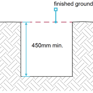
In frost susceptible soils, e.g. chalk, the depth to the underside of the foundation should be at least 450mm below finished ground level, to avoid damage from frost action.
Additionally, when construction is undertaken during cold weather the foundation should either be at least 450mm below finished ground level, or alternatively, precautions should be taken to prevent freezing of the ground.
Where the finished ground level is to be above the existing ground level and cold conditions are expected, the foundation depth should be taken from the existing, not finished, ground level.
Shrinkable and volume change soil
The design should specify the minimum foundation depth.
Table 1: Minimum foundation depths in shrinkable soil
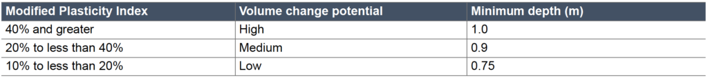
Shrinkable soils are classified as containing more than 35% fine particles (clay and silt) and have a Modified Plasticity Index of 10% or greater.
These minimum depths may only be used where any existing or proposed trees or shrubs are outside the zone of tree influence. Heave is possible in shrinkable soil where trees have been, or are being, removed.
4.3.4 Hazardous ground
Strip and trench fill foundations on hazardous ground shall be designed by an engineer, and notice given to NHBC before work commences.
Where hazardous ground has been identified, NHBC must be notified eight weeks before work starts. Hazardous ground is defined in Chapter 4.1 ‘Land quality – managing ground conditions’.
4.3.5 Setting out
Strip and trench fill foundations shall be set out to take account of the design details.
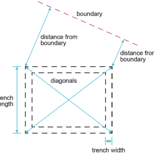
The accuracy of setting out should be checked by control measurements of trenches, including their location relative to site boundaries and adjacent buildings. Levels should be checked against accepted benchmarks.
For excavations, check:
- trench lengths
- trench widths
- length of diagonals between external corners.
Walls should be located centrally on the foundation, unless specifically designed otherwise.
Any discrepancy in dimensions should be reported promptly to the designer. Resulting variations should be distributed to all appropriate persons, including NHBC.
4.3.6 Services and drainage
All strip and trench fill foundations shall be installed to:
a) adequately protect existing services and ground water drainage
b) make allowance for drainage and other services.
Adequately protect existing services and ground water drainage
Any existing services, such as cables, water pipes or gas mains, may need to be supported and protected. Services should not be rigidly encased in the foundations, and drains which are redundant should be cut open and filled or removed. Precautions should be taken to accommodate the effects of settlement where drains run under, or near to, a building.
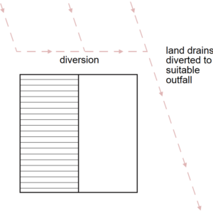
Provision should be made to divert or protect any existing ground water drains affected by excavation work.
Make allowance for drainage and other services
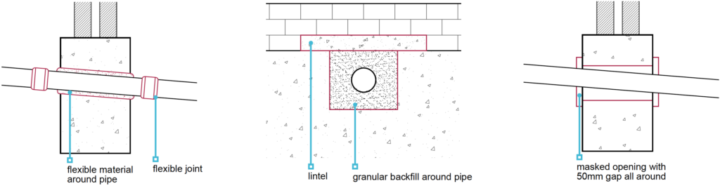
Where services are to pass through or above foundations, provision should be made for suitable ducts or lintels to enable later installation.
Strip foundations
Services should not pass through strip foundations but through the masonry above. Adequate lintels should be provided in the masonry.
Trench fill
The load-bearing capability of foundations should not be affected where services pass through. Services should be either sleeved or pass through a suitably strengthened opening in the foundation. This is to ensure that differential movement will not damage services.
For drainage, it is important to leave sufficient space for movement to ensure that the drain is capable of maintaining line and gradient.
4.3.7 Safe transmission of loads
Strip and trench fill foundations shall transmit loads to the ground safely and without excessive settlement, and take into account:
a) dead and imposed loads
b) foundation width and thickness
c) stability of any adjoining building.
Dead and imposed loads
Dead and imposed loads should be calculated in accordance with:
- BS EN 1991-1-1 – UK National Annex to Eurocode 1. ‘Actions on structures. General actions. Densities, self-weight, imposed loads for buildings’.
- BS EN 1991-1-3 – UK National Annex to Eurocode 1. ‘Actions on structures. General actions. Snow loads’
- BS EN 1991-1-4 – UK National Annex to Eurocode 1. ‘Actions on structures. General actions. Wind actions’.
- BS 648 – ‘Schedule of weights of building materials’.
All foundations should be:
- continuous throughout the building, including integral garages, porches, conservatories, bay windows, etc.
- symmetrical beneath load-bearing elements (i.e. walls should be located centrally on foundations).
Foundation width and thickness
The width of the foundation should:
- be of sufficient width throughout to avoid overstressing the ground, especially where the foundation is required to support piers or columns
- depend on the load-bearing capacity of the subsoil and the loads from the building
- not be less than the wall thickness, plus at least 50mm each side.
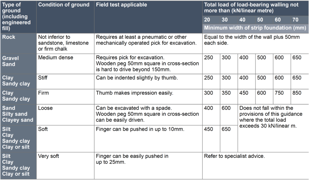
The width of strip foundations should account for ground conditions and be in accordance with the following table:
Table 2: Acceptable foundation widths
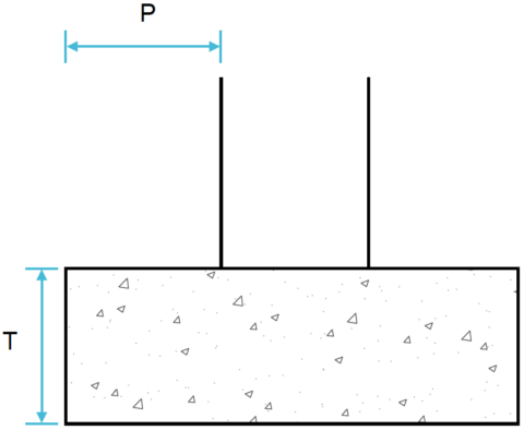
The thickness (T) of the foundation should be:
- equal to projection (P) or 150mm (whichever is greater)
- 150mm to 500mm for strip foundation
- 500mm minimum for trench fill foundations.
Stability of any adjoining building
Where foundations are taken deeper than an adjoining building, excavation and construction will usually need to be carefully supervised by the design engineer, to check the standard of workmanship. Where necessary, allowance should be made in the design for differential movement.
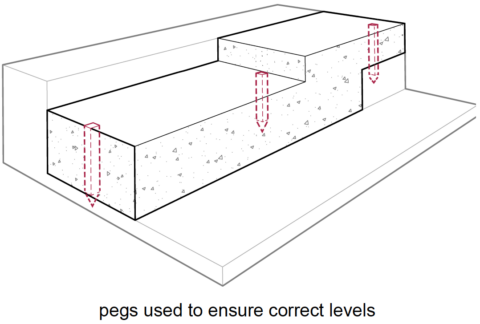
4.3.8 Sloping ground and stepped foundations
Strip and trench fill foundations shall be taken to a suitable bearing level when building on sloping ground, and steps shall be suitably formed.
Sloping ground may require stepped foundations. Where foundations are stepped, the height of the step should not exceed the thickness of the foundation,
unless it forms part of a foundation designed by an engineer in accordance with Technical Requirement R5.
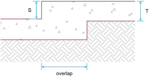
Foundation overlap
The overlap should be not less than:
Strip foundations
- 2 x S, or
- T (maximum 500mm), or
- 300mm, whichever is largest.
Trench fill foundations
- 2 x S, or
- one metre, whichever is largest.
4.3.9 Excavations
Excavations for strip and trench fill foundations shall:
a) take account of the design dimensions
b) take account of localised effects
c) be compact, reasonably dry, even and correctly shaped.
Design dimensions
Inaccuracy may prevent walls and piers from being located centrally and therefore result in eccentric loading of foundations and possible foundation failure.
Excess excavation should be avoided. Accurate trench digging is particularly important where the width of the foundation is only slightly wider than the wall to be supported.
Acceptance from the foundation designer is required where the foundation design is modified.
Localised effects
At soft spots, excavations should be deepened to a sound bottom or the concrete should be reinforced. Hard spots should be removed.
Where roots are visible at the bottom or sides of trenches, especially in clay soils, excavations may need to be taken deeper, or special precautions determined by an engineer in accordance with Technical Requirement R5.
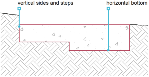
Compact, reasonably dry, even and correctly shaped
Unless otherwise designed by an engineer in accordance with Technical Requirement R5:
- trench bottoms should be horizontal, with all loose material removed
- trench sides and steps should be, as near as possible, vertical.
Trench bottoms affected by rain water, ground water or drying should be rebottomed to form a sound surface.
4.3.10 Reinforcement
Reinforcement for strip and trench fill foundations shall ensure the safe transfer of loads and be suitable for localised ground conditions.
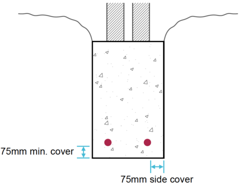
Reinforcement should be:
- appropriately sized
- placed correctly
- clean and free from loose rust
- secured at laps and crossings
- supported to ensure that they are 75mm above the base of the foundation or as indicated in the design.
If in doubt about any soft spots, the designer’s advice should be taken before placing the concrete.
4.3.11 Concrete
Concrete for foundations shall be:
a) of a mix which is suitable for the intended use
b) durable against chemical or frost action
c) correctly mixed, placed and cured.
Concreting should be carried out, as far as possible, in one operation, taking account of weather conditions and available daylight. Concrete should be placed as soon as possible after the excavation has been checked.
For trench fill foundations, it is particularly important to check that the finished level is correct and horizontal, as it is difficult to adjust for discrepancies in the small number of brick courses between the foundation and the DPC.
4.3.12 Movement joints
Strip and trench fill foundations shall have movement joints suitable for their intended purpose.
Where movement joints are specified, they should be continuous with those in the superstructure.
4.3.13 Construction joints
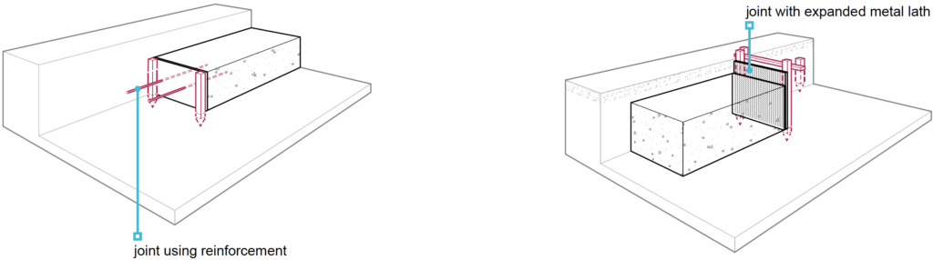
Construction joints in strip and trench fill foundations shall be suitably formed.
Where construction joints are unavoidable:
- they should not be positioned near a return in the foundation beyond the construction joint.
- all shuttering should be removed before work continues
Construction joints for strip and trench fill foundations may be formed by one of the methods shown above.